
Success has many fathers, while failure is often a bastard child, so stories abound about how closed loop BHO extraction got started.
Truth is also shorter than fiction, so let me share my perspective to consider with the rest.
I didn’t invent the concept, but instead got my inspiration 07-26-2009, 06:58 PM from a 04-26-2006, 08:13 PM post on IC Mag by Foaf, about how he used two paint pressure pots and a refrigerant recovery pump to extract cannabis with butane and recover it for reuse.
It was entitled BHO Large scale closed system and can be read at: https://www.icmag.com/ic/showthread.php?t=27954
There were no other systems posted at the time, but with my first visit with Fritz at Eden Labs, I learned that Fritz had been extracting with propane and recovering the LPG for reuse under CA Proposition 215 around 1997 and subsequently with Mathew Ellis in their Seattle facility.
Fritz and Mathew Ellis subsequently split, with Fritz pursuing super critical CO2, and Matt hydrocarbon extraction as Extract Tek. Those two are the two earliest closed loop extractors that I have been able to verify.
Here are the pictures FOAF posted in 2006, from which the Terpenator evolved:

FOAF’s experiment

FOAF Diagram 1


FOAF Diagram 3

From that I conceived the Mk I:
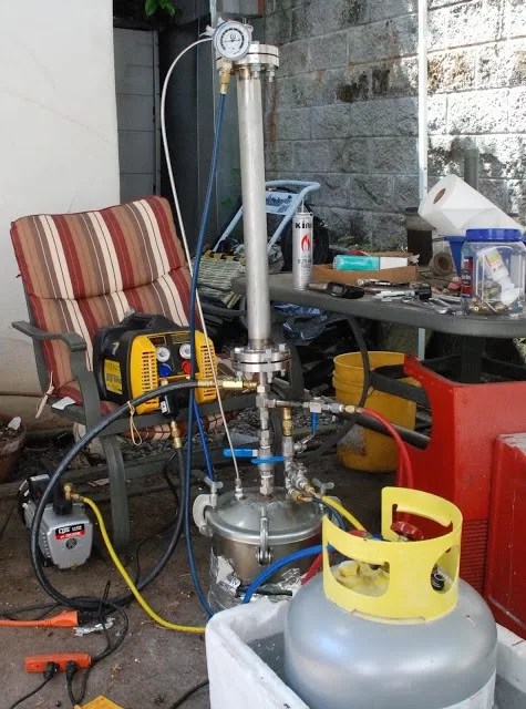
And built this prototype, using a such a deal bargain oil less refrigerant recovery pump, which was defective and I ended up replacing with an Appion, recommended by Ricky’s Bong on IC Mag.
Here is the lineup for show and tell pictures in my kitchen. Shown here with the 48″ column, made from Schedule 10 304SS pipe, with 4 bolt ANSI flanges that I had machined for an o-ring:

Mk I ready for trials with original pump and original Schedule 10 column.

Mk I shakedown run, which failed due to the pump.
First run after replacing original pump with an Appion refrigerant recovery pump.

Here is the yield from first successful run using a 1 1/2″ C 24″ column and scrap material:

The Mk I in production at the SPR Lab.

Here’s a 94.5 grams raw oleoresin extracted after shakedown, which we donated to a stage 4 Hep C patient, whom recovered and is still extant a decade later:
I posted the results on both Skunk Pharm Research site and at 02-07-2011 on IC Mag at:
https://www.icmag.com/ic/showthread.php?t=203067&highlight=Butane+extractor+recovery+system
6.9.3.2 The Mk II was the next Terpenator off the line and like the Mk I was based on a paint pressure pot, using a 2.5 gallon Bink’s stainless pot, but instead of building columns from stainless pipe, we used 1 1/2″ X 36″ stainless sanitary columns, and this one was fully automated after it was loaded and told number and length of cycles.
The controls were built by Pacific Semiconductor Inc (PSI in Portland) and used a PC, with adjustable pressure switches for set points.
The valves were all pneumatically operated and we installed the Mk II in a ventilated exhaust cabinet that pumped 3,500 cfm air in the top, and forced it out the bottom vents, giving it a face velocity of 194 surface feet and .4 air changes per second, or a full change every 2.5 seconds.
The controls and pneumatic solenoids were mounted exterior to the booth.

The Mk II ready for install.
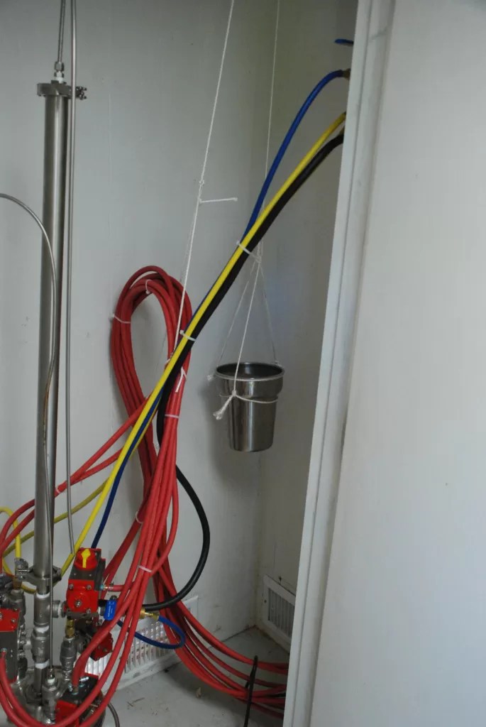
The Mk II installed in ventilation cabinet, with counterbalance for hoses.

Mk II Control cabinet.

Inside the Mk II control panel, showing the Programable Controller and adjustable pressure switches.

The air logic manifold and pass throughs.

Mk II program logic
As it came to pass, Sean from the land of CA, current purveyor of Ecogreen refrigerant, became interested in the Mk II and built one of his own and brought it to the SPR lab for startup and shakedown. Here is his unit as we shook it out outdoors at the Pharm:

Mk II clone by Sean during shakedown:

Sean’s control panel:

Sean’s Mk II pot:
Note that among other things, Sean used a different brand of stainless pressure pot.
6.9.3.3 Enter the Mk III! Perhaps the biggest quantum shift occurred when I noticed a couple of 6″X12″ 304SS sanitary spools at Glacier tank, which he had custom ordered for another customer, whom failed to pick them up.
I purchased them and conceived the Mk III, after which the cannabis extraction industry has never been the same. From those spools, I built the first Mk III Terpenator and Lil Terp. I posted those details online as well at both Skunk Pharm Research and IC Mag forum at:
Mk III at: https://www.icmag.com/ic/showthread.php?t=245953&highlight=Terpenator
Lil Terp at: https://www.icmag.com/ic/showthread.php?t=240005&highlight=Terpenator
I say the industry has never been the same because not only did others start to build the Terpenator internationally, but as soon as we ordered some parts custom built in China, the Chinese jumped right in and started offering the parts already machined and welded direct.
As is typically the case, the machined and welded assemblies from China cost little more than the material cost included, springing a new market.
I supported Terpenator startups in at least four other countries besides the US of A based on the Mk III design. In the US, I helped Specialized Formulations and Terpp Extractors with their startup.
The exciting news is that once my brain fart (epiphany) was revealed to the fertile minds in the cannabis culture, any number of lights went on and variations sprung up by different manufactures, centered around sanitary components originally intended for the brewery industry.

Original Mk III lid machining detail, based on a 6″ sanitary tri-clamp end cap.
Here are the balance of the modified parts:

Balance of machined parts:

Here is the lid assembly:

Injection Tee

Parts from Glacier Tank, machined by Moody Machine Works, and welded by Gibson Welding. Received and loosely assembled in my kitchen:

Here is the shakedown run on the Mk III prototype.

And the yield from the pilot run was good considering, we used poor grade trim.
Part of our research at Skunk Pharm Research, was supplying cannabis essential oil pro bono to end of life and other seriously ill patients, and as a result we sometimes received large trim donations and met on weekends to wade through it collectively as a group.
Below is such a gathering with both the Mk I and the Mk III prototypes dueling to see which had the greatest thru put. You can see that by the time this was taken, the original Mk I prototype had become the Mk IA, because we had replaced the original Schedule 10 columns with ANSI four bolt flanges, with sanitary triclamp columns, similar to what we used on the Mk II, and it has heating cable wrapped around the column.
The Mk III doesn’t have column heating, but still produced more per hour under the same conditions, using a 24″ column.
More history at:https://www.icmag.com/ic/showthread.php?t=245953&highlight=Terpenator

Dueling Mk I and Mk III Terpenators
6.9.3.4 The Mk IV Chimera, Mk IV Phoenix, and Mk IVC
Because of the limited evaporation area afforded by a vertical 6″ sanitary spool, I conceived the Mk IV Chimera, which used two 6″ X 12″ sanitary spools turned on their sides for the collection tank. While I mocked one up, I didn’t follow through for a couple reasons.

Mk IV Chimera conceptual
The first is that it is a tongue in cheek compromise because although the tanks offer copious surface area when half full, their surface area reduces as the level drops, due to the curved walls of the tube lying on its side.
The Mk IV Phoenix was the second Mk IV, and I conceived it when the Mk III demand overcame Glacier Tanks reluctance to order 10″ and 12″ X 12″ sanitary spools. I scrapped the Chimera design and went with the Mk IV Phoenix design instead, based on a 10″ pot, and added the Mk V based on a 12″ pot.
I ordered ten Mk IV and ten Mk V kits from China, fully machined, welded, and ready for assembly.
More history at:
Mk IV @ https://www.icmag.com/ic/showthread.php?t=276157&highlight=Terpenator
Mk V @ https://www.icmag.com/ic/showthread.php?t=274340&highlight=Terpenator

Mk IV Phoenix prototype.
My next step was to have the Mk III, IV and V designs peer reviewed and certified to meet ASME Section VIII, using an independent ME PE, and then the fun began.

Mk IIIA ASME Section VIII Certifications by Chilton.

Mk IVB ASME Section VIII certifications by Chilton:

Mk VB ASME Section VIII certifications by Chilton:
I also applied for and received the registered trademark for Terpenator:

Terpenator Trademark:
6.9.3.5 The Mk V, Mk VA, Mk VA2, VB, & Mk VC
A friend asked me to build him fully automated Mk VA beta unit, to which I agreed to do for the experience, if he would pay for the actual development and build costs.
About that same time, my son asked for support founding WolfWurx, and pacts were made. Resulting in the Mk VA.
I had the stainless cart built at Trilett in Oregon City, and assembled the unit in their shop, but before it was complete, I was importuned by another friend to build him a manual Mk V beta unit quick like a bunny for the fun of it.
I again agreed for the experience, and Trilett was able to respond with another cart quickly enough that the manual unit did ship within the requested schedule, and before the fully automated one, because of less complexity.

Johnny 5, first WolfWurx Mk V:
She was affectionately named Johnny 5 by her proud new owner, and here is a peeecture of her first production run, that demonstrates his enthusiasm and says a lot about why he felt that way.
Operating his manual machine also helped me in developing a program for the Mk VA close behind.

Johnny 5’s first production run with prime material:
The Mk VA was not given birth so easily, but with PSI Bob’s stalwart electronics support, Brians programing support, and serendipity, she rolled out of my garage where I had installed the finishing touches.
Instead of using a programable controller, Bob designed and built our electronics package from scratch components, and was able to cajole Brian into programming the chips. That is where the serendipity comes in, as Brian programmed Microsoft’s Pentium I through IV chips, and was available to me only because in his youth, Bob mentored him during his apprenticeship.
Once we had shaken the new board out, I replaced the original programmable controller controls in the Mk II with our own custom board.
I was able to shake her out and develop the process, by setting up a popup canopy with privacy panels in my driveway, and we were able to load her in the back of Siskiyou Sam’s pickup afterwards with grunt power, loading the cart and then the ancillary components.
Sam subsequently lovingly named her Beta Bitch, as we refined her and worked through the details of her idiosyncrasies.

Here is Beta Bitches frame with Mk V kit mounted, using pneumatically controlled valves.

Beta Bitch ready to ship, with everything mounted and shaken out.

Beta Bitch’s controls and logic manifold, run by chip with proprietary programming.

Controls by PSI, wiring by MOI. Below is Beta Bitch’s backside peeecture.

Beta Bitch’s cute butt:

Beta Bitch’s collection pot and dump valves.

Here is Beta Bitches first production run on scrap material:
And lastly, a peeeecture of Beta Bitch posing with the first Mk IV and V prototypes assembled from parts we imported directly from China.

Beta Bitch with examples of Chinese Imported kits:
Which brings us to the next chapter, when I helped my son start up WolfWurx, Inc, whose mission was to develop and market the Terpenator product line, and we ordered (10) Mk IV and (10) Mk V parts kits built in China by Wenzhou Kingstone Valve and Pipe Fitting Co, ltd.
The overall quality was good, with some shipping dings and we sold some off as kits and built some complete turnkey systems using the kits as the central core.
By the time they arrived, we had moved our manufacturing operation from Trilett in Oregon City, to Insta Fab in Vancouver, where they did an excellent job of building our carts for us and tolerated us doing primary assembly in their shop:

Mk IV and V kits imported from China at Instafab:

WolfWurx Mk V’s undergoing assembly at Insta Fab:
All the machines were finished in my garage, and the next WolfWurx machine to go out the door was Jenny, a Mk VB2 using both an Appion and a diaphragm recovery pump.

Jenny, Mk VB2 with diaphragm recovery pump.
Jenny was plumbed as follows:

Jenny, Mk VB plumbing diagram:
Jenny was the only Terpenator built using a diaphragm pump, with the next standard Mk VB’s plumbed as follows:

Mk VB plumbing diagram:
Next we added a tri-coil heat exchanger for chilling injection and pump exhaust using alcohol and dry ice, or a process chiller. It had one core for cooling pump exhaust and two coils for cooling the incoming LP at injection.

WolfWurx Mk IVB and VB Tri-core heat exchanger:

Beast, Mk VB, pre-distilling Butane, using a Tri-core heat exchanger.
Double, double toil and trouble;
Fire burn and caldron bubble.
Fillet of a fenny snake,
In the caldron boil and bake;
Eye of newt and toe of frog,
Wool of bat and tongue of dog,
Adder’s fork and blind-worm’s sting,
Lizard’s leg and howlet’s wing,
For a charm of powerful trouble,
Like a hell-broth boil and bubble.
Double, double toil and trouble;
Fire burn and caldron bubble.
Cool it with a baboon’s blood,
Then the charm is firm and good.
Macbeth: IV.i 10-19; 35-38

Mad Shatter, Mk VB with Tri-core heat exchanger:

Big Bad Wolf, Mk VB with Tri-core heat exchanger:

R2Weed2, Mk VB, last WolfWurx Mk VB.
The last Mk VB was SN-000012 R2Weed2, certified to ASME, IBC, IEC, and NFPA-58 in WA WA land by Kirkland Dynamics.
Returning to the subject of automated units, the next automated units out WolfWurx’s door, were Bertha and Mary, the only Mk VA2’a built. They performed a complete cycle in about 2 hours and 11 minutes.

Mk VA2 PID

Bertha, Mk VA2 strutting her stuff:

Bertha and Mary, dueling Mk VA2’s:

Mk VA2 front shot:

Mk VA2 control panel:
Mk IVC/VC:
Enter Medizin from Las Vegas, whom I built Medizin Maker for, the very first Mk IVC and the first unit to be certified to meet not just ASME, but IBC, IEC, and NFPA-58 in OR, WA, CO, NV, and MD by Pressure Safety Inspectors, LLC (PSI) in CO. They certified the Mk VC at the same time.
Medizin Maker was originally built as a Mk IVB with counter flow heat exchangers, vis a vis Tri-core, with a standard vacuum pump, and conventional ASME BPE pressure pot, but when we attempted to certify it for use in NV, their evolving requirements, forced me to upgrade the design and the Mk IVC/VC’s were born.
Fortunately my customer worked with me, and I simply bought the components back from him that needed upgrading, and he paid for the upgraded parts.

Mk IVB PID with Tri-core heat exchangers

The Mk IVB with counter flow exchangers
The WolfWurx, Mk IVC was similar to the Mk IVB, except for upgrades to the components used and addition of three more PRV’s.
We upgraded to a custom collection pot with placard, by an ASME tank manufacturer, increased the wall thickness on the stainless tubing, including the counterflow heat exchangers, so as to be able to get it certified by PSI to ASME, IBC, IEC, and NFPA in OR, WA, CO, NV, and MD.
After WolfWurx was traded to Pioneer Holding, the subsequent Pharmgold Mk VC was also made to the same specifications, but built by Pharmgold rather than WolfWurx.
However, here is the certification cover sheet for the WolfWurx certifications from PSI and some pictures of Medizin Maker, SN00013 and final WolfWurx production.

WolfWurx Mk IVC/VC PSI certifications for Oregon, Nevada, Maryland, and Colorado:

Medizin Maker SN00013. The last WolfWurx built unit.
The Mk IVC incorporated the same Haskel EXT-420 recovery pump used on the Mk IVB, both plumbed so that it can be used in either single or double stage. As it is pneumatic, it meets NEMA 7, Class I, Div I requirements.

The venerable Haskel EXT-420 plumbed for both single and double stage recovery:

Plumbing the Haskel to run either single or double stage.
The WolfWurx Terpenators all used N2 backfill so that when the system was opened, it was below 10% of Lower Explosive Limits (LEL).

Nitrogen backfill:
One of the biggest design departures, was replacing the electric vacuum pump with a pneumatic one. The Mk IVC switches to a Vaccon Series 300 venturi vacuum, which has no moving parts and is NEMA 7, Class I, Div I. It will evacuate to -29.5″ Hg on 80 psi air pressure and 22 scfm.

The Vaccon HVP 300 Series pneumatic vacuum pump:
Another new feature was the choice of either a Binks ASME pressure pot, or a ASME pressure pot custom made and certified by Marks Brothers. Here is a conceptual of a custom built pot, as well as a picture of a Mk IVC with Binks pot.

12” Pressure Pot Conceptual

Binks pressure pot being used in this application.
One mid production change in the Mk IVB/VB design, was adding a cyclonic filter drier on the inlet of the pump and removing the mol sieve filter drier after the pump.
The design was not only effective in removing water from the LPG, but was highly effective in protecting the pumps against inadvertent flooding with liquid LPG containing essential oil, a death knell for the piston seals.
The vessel shown holds two #48 filter zeolite filter drier inserts, which can be recycled by baking under vacuum, or is easily replaced without all the dust issues associated with Mol Sieve.

Mk IVB/VB and IVC/VC Cyclone Dryer Filter

The high-pressure clamp required to meet 350 psi ASME Section VIII requirements on the 6” Cyclone Filter in LPG application:
Another big change was moving from the off the shelf counterflow heat exchanger, to custom built units. To certify the Mk IVC, I had to upgrade the Mk IVB counter-flow exchanger to get the required .049 minimum wall thickness on the 1/2″ stainless tubing. The extra wall thickness is required, despite the grossly over pressure rating of the .035 wall tubing, as a hedge against extrusion defects in the tubing.
I had them custom wound by Albina Tube in Tualatin and used modified Swagelok compression tees to finish them off.
No change in operation from the Mk IVB, as the injection heat exchanger still uses a counter-flow exchanger using liquid N2 as the refrigerant on the jacket side, and drops the injection temperature to between -30C and -50C. There is a thermocouple in the discharge that tracks that temperature.

The second one cools the pump discharge, using a Temco Fisher Merlin 150 -15C process cooler. The coolant discharge from the counter-flow exchanger is subsequently routed through the heat exchanger coil in the storage tank bath, to keep the tank temperature around 0C/32F.

Mk IVB Counterflow Heat Exchangers

Storage tank cooling coil, that uses the discharge from the counter-flow heat exchangers above.
And of course we had to add multiple pressure relief valves, some of them with a check valve in front, to handle vacuum. Swaglok custom designed this assembly for us, which we used on all the Mk II’, IV’s and V’s.

Swagelok pressure relief valve with check valve isolating it from vacuum:
Lastly, everything that wasn’t NEMA 7, Class I, Div I was relocated to an adjacent equipment room.
Both pot heat and column heat are provided using hot water, heated and maintained by our in house designed inline heaters. The pot heat has a 2kW heating element and the column heat has a 6kW element. They are both controlled by Type J thermocouples and PID controllers.
They are skid mounted for installation ease and share the equipment room with the Merlin 150 process chiller and the Polar Air screw compressor.

Mk IVC equipment bay
The pot heater just recirculated the water in the pot bath, so the volume never changes, but the column heaters have to go from circulating mode to flooding an empty column without cavitating the pump, so has to have extra hot water volume available to it. I accomplished that by adding a surge tank in front of the pump, which could be refilled between uses.
Here’s the original prototype inline heater. It uses a 1/3 hp hot water circulation pump right out of the Grainger catalog, a 1/4″ Type J tubular thermocouple, and a 2kW heating element from Grainger. We subsequently redesigned the lid on the Pharmgold unit, to use a different brand and size element, but I don’t have that print or information.

Mk IVB/VB inline heater for column heat
https://www.youtube.com/watch?v=CTrjPButrVc
https://www.icmag.com/ic/showthread.php?t=332962&highlight=Terpenator
Moving right along, WolfWurx, Inc was traded to Pharmgold and Medizin Maker, Mk IVC SN00013, was the last unit built by WolfWurx. Some of the upgrades required for certification were actually finished at Pharmgold after the trade, and the unit was shipped with a WolfWurx name tag and serial number, but with Pharmgold labeling.
Here is Medizin Maker as she shipped to Pharmgold, before any upgrades.
Note that this picture doesn’t show the new Marks Brothers ASME pressure pot, or the new counter flow heat exchangers.
Notice all the Swagelok valve handles are color coded to aid the operator in rapidly recognizing them, and this turned out to be a good feature.

Medizin Maker leaving the WolfWurx lair and heading to Pharmgold

Graywolf with the first and last unit manufactured by Pharmgold, a Mk VC, SN PG000014.
6.9.3.6 The Mk VI
Besides the Mk I through Mk V, there were designs for Mk VI through Mk VIII that were never built. I actually did the Mk VI conceptual for a customer, who changed jobs in the middle and the project fell by the wayside when he left.

Mk VI Terpenator
6.9.3.6 Mk VII Terpenator
Here is the schematic for the Mk VII, which is a system incorporating inline dewaxing. The Mk VIII used cold boiling to achieve the desired temperatures, but I replaced the design with the Mk VIII after I determined that a high percent of Propane was required in the mix, for it to operate at the temperatures desired. Here is more history:
https://www.icmag.com/ic/showthread.php?t=285460&highlight=Terpenator

Mk VII conceptual
6.9.3 The Mk VIII
Below is the conceptual for the Mk VIII inline dewaxing column, which uses a shell and tube heat exchanger to chill the solution, and then vacuums it through a 4″ X 8″ polyester felt 1 micron sock filter to remove the plant waxes that precipitate out.

Mk VIII Dewax Column Conceptual
The refrigerant side of the shell and tube uses a -40C process chiller. The filter section is also kept at -40C, using a stainless coil and insulated jacket.
The Mk VIII was never built, though I completed the detail prints and shared them with Sweetleaf and one of the sanitary steel companies to price out in China.
Sweatleaf developed their own version of the sock filter and I lost track and interest in the rest at the time, because I was seriously busy closing out WolfWurx business and our Terpenator was designed around not extracting the plant waxes in the first place, so a dewax column wasn’t required.